In preparation to complete the design of a relatively precise LM3900 F/V convertor for electronic music applications, I was working on resolving how to make differential comparisons with precision using the LM3900. A lot because the +In and -In of this Norton opamp match best when the input currents are both 10μA. But with dynamic signal inputs, a constantly fixed matching current is impossible. A browse through AN-72 revealed an interesting circuit for a more precise voltage comparator, Figure 69.
I built and tested the comparator, using a LM4040AIZ-10.0 as a +10.00V voltage reference. The comparator had to be tested with low audio frequencies, because the default output voltage swing for +15V supplies is +14.5V. Given the slow and asymetrical signal swing of the LM3900, this sort of comparator cannot be fast. However, the Figure 69 circuit configuration lends itself to a DC amplifier amplication with precise offset, as well as for a differential integrator with more precision, compared with the Difference Integrator depicted in Figure 83 of AN-72.
Here's my lab notebook, replicating first the circuit of Figure 69:

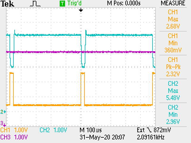
While the edge rates were incredibly slow, there were nonetheless very accurate. The switching action occured extremely close to the +5.00V Vref, a voltage derived from the LM4040 +10.00V reference.
The first circuit modification was to change the action of the comparator to that of a linear amplifier, by adding a negative feedback resistor. This was quite successful, and further this amplifier has a precise positive voltage offset set by the +5.00 Vref into a matching -In input, which the circuit of Figure 69 relays as a matching voltage to cause matching currents to flow into the +In inputs of the target opamp, as well as the "mirroring" opamp which is assisted by a further inverting gain stage with a simple transistor circuit. So, nicely enough, in all cases, negative feedback is holding everything in place. The use of negative feedback, and 1% resistors allows good precision. The composite solution is not sensitive to AC hum, nor stray signals, despite the use of 1MΩ 1% resistors. Some tests were done with AC signals on top of the precision offset voltage. The circuit does not allow inputs below 1 Vbe, due to the lack of common-mode resistors added to the inputs. However, it was easy to see the test generator signal (from a Tek FG-502 Function Generator) be normalized to the +5.00V baseline offset voltage.
A set of tests was done with about 20 KHz sinewaves close to 2Vpp, as well triangle signals. The sinewaves work well (though the circuit is unloaded) at 20 KHz, but we see a little bit of amplitude loss with triangle waveforms. Lower frequency sawtooth and pulse signals of similar amplitude were also tested. In all cases the gain was also precise, +1.0, due to the 1% gain-setting resistors R2 and R9.
A set of tests was done with about 20 KHz sinewaves close to 2Vpp, as well triangle signals. The sinewaves work well (though the circuit is unloaded) at 20 KHz, but we see a little bit of amplitude loss with triangle waveforms. Lower frequency sawtooth and pulse signals of similar amplitude were also tested. In all cases the gain was also precise, +1.0, due to the 1% gain-setting resistors R2 and R9.


What was being looked for though was use of the matching of two indentical -In inputs from two different opamps as a "matched set," which due to monolithic construction of the IC, do exist on the LM3900. This is helpful for a use in a charge-balancing V/F circuit design being contempleted. So, a further test was done by replacing the feedback resistor with a 0.0068μF capacitor, so as to construct an equivalent version of the Difference Integrator depicted in Figure 83 in AN-72. Due to the feedback action with the "mirroring" opamp, both the Vref and the signal generator signals are both provided to matching -In inputs on a monolithic, greatly improving precison matching. Another circuit design aspect demonstrated here was the simultaneous processing of a separate DC and AC signal path, with precision results. For a charge-balancing V/F convertor, the Vref input would be switched in a feedback circuit driving the V/F oscillation. Precision matching is of very great value for linearity and frequency precision, a necessity for pitch-accuracy in electronic music.

Comments
Post a Comment