This was a circuit taken directly from AN-72, Figure 86, and implemented on a solderless breadboard, to see how well it would work.
It was just amazing! It's a sample-hold that automatically compares a held voltage with a new Vin. And when sampling, it also tracks the input with constant delay up to the integrator rate limits, using feedback from a servo loop. Moreover, it's a comparator that provides the tracking control feedback. That output is really interesting also -- esp. for electronic music applications. This AN-72 application circuit in general is a nice showcase of how the LM3900 can implement a servo loop to enable a unique single-supply application.
The function was being examined as a possible way to implement an ADSR envelope generator. It turned out to not be so useful for that application. However the since the tracking capability can follow an input voltage, it is in fact useful for holding the output steady for a differential integrator against a DC value, such as the Sustain voltage in an ADSR.
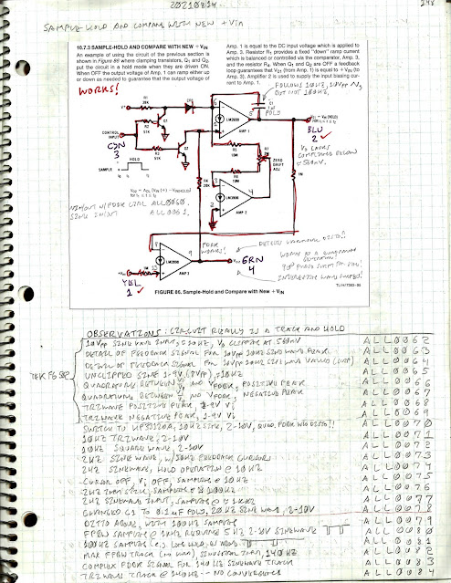
Some description of these features are in order. First, here is the main page of the engineering notes, and following that will be additional technical description and scope fotos.
Main Engineering Notes
First glimpse: 10Vpp input (ORN), tracking output less Vos (BLU), and internal servo (GRN)
In it's present form, this circuit design cannot accept Vi < Vbe, so it shows the output clamped at ≈560mV, bacause it's lacking in compliance. The input was a ≈10Hz sine wave from a Tek FG-502, which was used because it allowed certain conveniences for offset voltage. In the first few tests, the sample-hold is programmed to only sample (e.g. track) the input waveform.
It is quite interesting to watch how the servo loop responds to both the sine wave peak, and also the clamped Vi. The next two scope fotos illustrate the phenomena.
Detailed servo loop response to +10V peak of sine wave
Detailed servo loop response to 560mV clamped Vi of sine wave
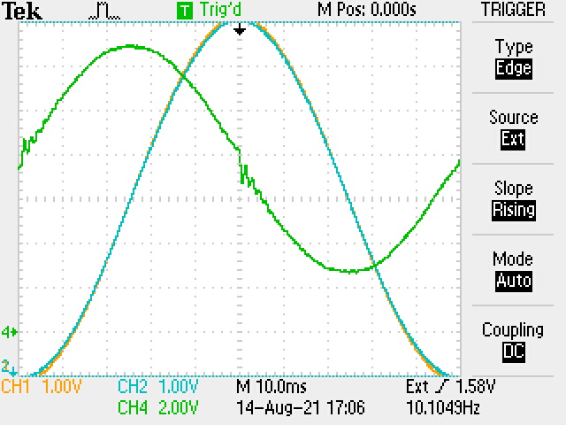
The input waveform was readjusted to 8Vpp, from 1-9V, again at ≈10Hz. Now the output is fully tracked with a constant delay. Some interesting phenomena starts to emerge in that the servo feedback waveform is oscillatory, but it also is taking on a quadrature aspect, creating a cosine wave to match the sine wave. As will be shortly seen the quality of the sinewave (e.g. relative distortion levels) are made manifest by the servo loop!
Tracking I/O (no hold cycles) plus feedback
Feedback response to +9V peak of sinusoidal input

Feedback response to +1V valley of sinusoidal input
What is seen is that the inflection points, when the waveform reverse direction, there is an oscillatory reponse in the servo loop. Otherwise, along other points, the servo loop produces a quadrature sinusoid.
The Tek FG-502 internally has a sine shaper composed of a 4 diode bridges with separate breakpoints affecting both the negative and positive cycles of the internal triangle generator. The specified sine wave distortion from 0.1 Hz to 100 kHz is 0.5%. Most probably, my particular unit is out-of-calibration, and it has been in service likely since 1974.
Watch what happens when the FG-502 source is replaced with the HP 33120A synthesized function generator, which offers significantly less distortion. The input sinusoidal waveform was set to swing from +2 Vto +10V.
Feedback response to HP 33120A sinusoid: clean quadrature
The servo feedback signal is an extremely clean quadrature waveform in relation to the input! So, this gives an inkling that the servo loop output of the sample-hold has some waveform signal processing utility. In the present case, amplifying distortion components of a sinusoidal input waveform.
The FPBW of this circuit does depend on the overall op amp loop gain, as well as the capacitor size. Using the 1µF capacitor was limiting the low frequency tracking response, and also thereby the range of frequencies that could be used to sample the input (e.g. actually hold a signal). The capacitor was replaced with a 0.1µF capacitor for higher bandwidth.
8Vpp signal increased to 20Hz with 0.1µF sample-hold capacitor change
The servo loop still responds in quadrature to the faster 20Hz wave, but now it has a lower amplitude. This is in keeping with effectively the bandwidth response of this feedback loop.
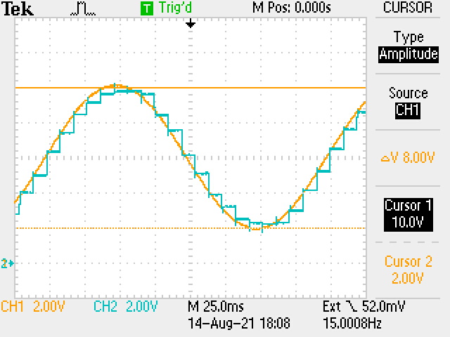
Now finally we put the sampler to work, actually sampling an input waveform:
100Hz periodic holds of a 15 Hz sinusoid
In a synthesizer context the sample-hold is useful for sampling waveforms to produce control voltage sequences for other modules. The servo loop which provides the tracking though looks useful as a control voltage generator. Not only that, but it also seems to have interesting waveform signal processing capabilities. In essence, the servo loop produces an Integral of the input signal, multiplied by a constant that is frequency dependent. A cosine wave is produced for a sine wave, and a square wave is produced for a triangle wave input. The frequency limitations could be expanded by allowing smaller integration capacitors. This might range up to 1-2 KHz. When the input frequency has spectral components outside the loop bandwidth, not only is the feedback more oscillatory, but also the tracking output becomes misconvergent. This would of course introduce errors when sampling. For use of this circuit concept at an audio rate, it would be interesting to construct the circuit using a wideband LM359 Norton op amp.


Comments
Post a Comment