The Schmitt Trigger in the AN-72 triangle wave generator does an essential role: It sets the switch points for the triangle wave integrator, and it controls the state of the current charging cycle, through regenerative action. It acts like two voltage comparators driving one flip-flop, but does so with just one op-amp. So, a Schmitt Trigger offers an economy of the resources used to construct a triangle wave generator.
After improving the switching speed of the LM3900 Schmitt Trigger for use in a VCO application, it was desired to improve the switching precision, to improve the tolerance against +Vbe change with temperature, as well as not rely on the +15V power supply as a precise reference voltage.
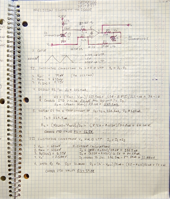
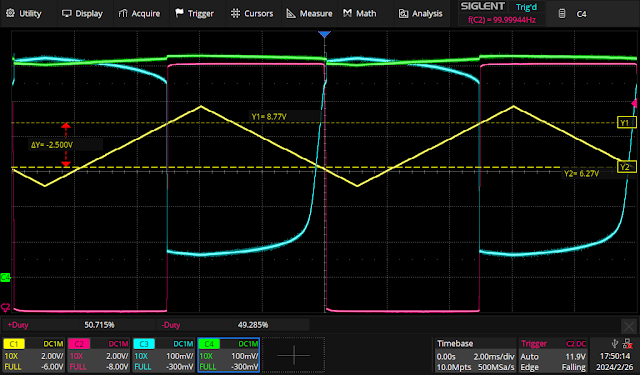
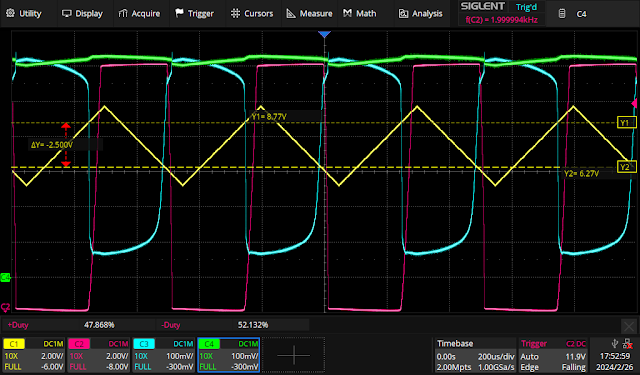
The test circuit in the engineering notes below accomplishes both precision and speed, at least for a LM3900. The goal was to switch with ΔV of 2.50V centered at 7.50V, which is nominally ½ of the +15V power supply voltage. So: the UTP ≡ 8.50V, and the LTP ≡ 6.25V. This ΔV limits the integrator in the LM3900 triangle generator of the VCO so that an undistorted triwave is possible in excess of 20 KHz, given the 0.5V/µS slew rate limit of the op amp.
The first observation to improve precision is that the switching at the UTP from low-to-high is implemented against the reference current used at the -input. To make this much more precise, a LM4040AIZ-10 10V voltage reference is used. This sets a more precise current value against which the the current from the input is compared, in contrast to using a regulated +15V power supply voltage. Also, the reference voltage is immediately local to the LM3900 package, and not distributed over long runs of wire from the power supply, which can incur (small) IR drops.
As this is a positive Schmitt Trigger (e.g. the input waveform polarity is followed by the output waveform polarity), the regenerative switching from low to high after reaching the UTP sets up the hysterisis needed for the LTP. Switching all the way to Voh with the LM3900 incurs a time penalty due to the rise time being much longer than fall time. Rather than rely on switching all the way to the considerable Voh to set the LTP, and to set a precision current to enable the LTP, a second voltage reference is used, a LM4040AIZ-2.5, which is a 2.5 volt reference. The output of the LM3900 reaches +2.5V much faster than the typical 14V Voh, so the output is used to turn on a reference diode clamp (the LM4040AIZ-2.5), and that precise clamped voltage is used for positive regenerative feedback, and the current required to setup the LTP. By balancing resistor values, the ΔV from UTP ⇒ LTP can be set to precisely 2.50V.
The engineering notes for the circuit design and characterization data are above. Exemplary scope fotos follow next.


Comments
Post a Comment